

How to Specify an Ultra-Thin Magnetic Track Light System for Commercial Projects
An ultra-thin magnetic track light system should be specified as a coordinated package. The rail, power feed, driver, connectors, light modules, and controls all depend on the same electrical and mechanical interface. A mismatch can delay installation, limit dimming, or leave a project with fixtures that do not fit the installed rail.
Settle five points early: ceiling conditions, mounting method, system voltage, connected load, and module compatibility. The process below turns a lighting concept into a specification that a manufacturer can quote and sample.
What Is Included in an Ultra-Thin Magnetic Track Light System?
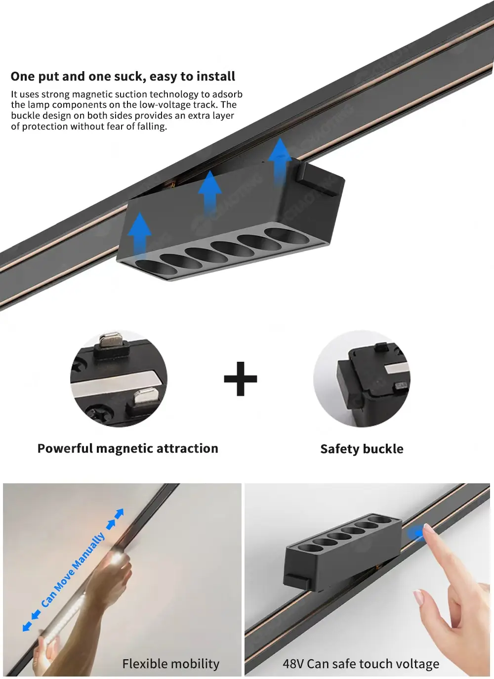
A complete schedule should identify every component needed to carry power, form the layout, mount the luminaires, and control the light. Treat the selected product family as one platform through future replacement orders.
Track Rail and Electrical Conductors
The track rail provides mechanical support and distributes low-voltage DC power. Record its width, height, standard lengths, finish, conductor arrangement, mounting type, and cutting instructions. These details affect the ceiling section, fixing method, joint positions, and visual result.
Layout drawings should show straight and corner connectors, end caps, power feeds, and suspension parts. Confirm the polarity path, joints, and feed points before ceiling work starts.
Driver, Power Feed, and Connectors
The driver converts the building supply to the DC voltage used by the track. Its rated output, dimming method, installation location, ventilation, and service access belong in the specification. A concealed driver still needs an accessible location for inspection or replacement.
Ask the supplier to mark each power feed and connector on the layout and include its quantity in the quotation.
Magnetic Light Modules and Controls
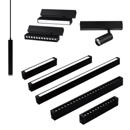
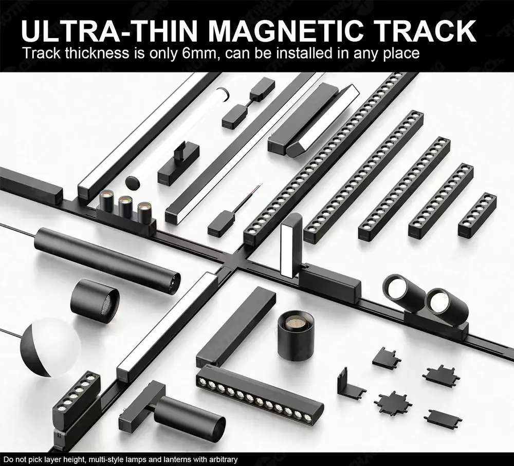
A single rail family may accept spotlights, grille lights, linear modules, flood modules, and pendants. Each module creates a different distribution, so the fixture schedule should connect every model to a lighting task. It should also state wattage, lumen output, beam angle, color temperature, color rendering, finish, and control type.
Specify whether the project uses simple switching, whole-run dimming, group control, or individual fixture control. Match the modules, driver, and controller to that requirement.
Which Mounting Method Fits the Project?
Choose the mounting method from the building condition and construction sequence. Ceiling material, available depth, access above the ceiling, desired track visibility, and installation timing determine which rail profile can be fitted reliably.
Surface-Mounted Track
Surface-mounted rail fixes directly to a finished ceiling or wall. It is useful for concrete ceilings, renovation projects, rental units, and sites where cutting a recess is impractical. The installer still needs a level fixing surface, suitable anchors, an agreed power-entry point, and enough space for the driver.
Sampo Lighting’s M26 surface-mounted magnetic track rail measures 26 mm wide by 6 mm high. The product page lists black and white finishes and standard lengths of 1 m, 1.5 m, 2 m, and 3 m. These options allow the rail schedule to reduce unnecessary joints while fitting the room dimensions.
Recessed Track
Recessed rail is coordinated with the ceiling framing and finish. Confirm the opening size, installation depth, trim detail, screw positions, joint alignment, power feed, and finishing sequence. A full-size sample can show how the rail meets the ceiling finish.
This decision belongs in the reflected ceiling plan before the ceiling is closed. Late changes may affect framing, wiring, plasterwork, and access to the power supply.
Suspended Track
Suspended track lowers the lighting plane from a high or open ceiling. State the suspension length, fixing points, spacing, load limits, cable routing, and finished height.
Check level and alignment across the full run. Small height differences become visible when several slim rail sections form one continuous line.
How Should You Match Voltage, Driver Capacity, and Controls?
Electrical planning begins with the selected product family. The same voltage marking does not prove that rails, modules, feeds, or control parts share an interface. Use the manufacturer’s documented combinations and keep a record of the approved part numbers.
Confirm the Complete System Voltage
List the building input voltage and the track operating voltage separately. Then confirm the rated voltage of the driver, rail, light modules, power feeds, and control devices. Sampo Lighting groups a range of rails and luminaires under its 48V magnetic track light system, including surface and recessed rails, spotlights, grille lights, and flood modules.
Written confirmation should cover conductor layout, polarity, adapter dimensions, mechanical locking, communication protocol, and connector design for every proposed component.
Calculate the Connected Load
Create a fixture schedule for each powered run. Multiply the wattage of each module by its quantity, then add the results:
Connected load = sum of module wattage × module quantity
Compare that total with the driver’s rated continuous output and apply the manufacturer’s required reserve. Record the planned load, permitted load, and spare capacity.
Ask the supplier to confirm the permitted run length, loading conditions, conductor capacity, voltage-drop limit, feed points, and cable size.
Specify the Control Method
Define whether the project needs simple switching, synchronized dimming, separate zones, adjustable color temperature, scheduled scenes, or individual control. Record the selected protocol and wiring plan.
For TRIAC, 0-10V, DALI, Zigbee, Tuya, or another platform, request a system diagram and working sample. Test minimum dimming, startup, synchronization, visible flicker, and power-loss recovery.
How Do You Select Light Modules for Each Lighting Task?
Divide the plan into ambient, task, accent, wall, and decorative lighting zones. Select modules from the approved rail family for each zone, then verify the effect through photometric files, calculations, and samples.
Linear and Flood Modules for General Illumination
Linear modules can form continuous visual lines or illuminate circulation areas. Flood modules spread light across wider zones and vertical surfaces. Review effective lumen output, distribution, spacing, glare, module length, and dark gaps between fixtures.
The ultra-thin magnetic track light system category includes linear, silicone-strip, and wide-area flood options. Use exact model data because wattage and distribution vary.
Spotlights and Grille Lights for Accent Lighting
Spotlights direct attention to products, artwork, signs, counters, or architectural details. Grille modules can provide several controlled beams in a compact body. For each target, record mounting height, aiming distance, target size, beam angle, lumen output, color temperature, and CRI.
A narrow beam creates a smaller, brighter pool of light. A wider beam covers more area. Test the proposed optic on the actual merchandise or finish.
Pendant Modules for Decorative and Task Lighting
Pendant modules bring the source closer to tables, counters, and reception points. Record dimensions, suspension length, mounting height, glare control, and wattage. Check sightlines from seated and standing positions.
What Compatibility Checks Should Be Completed Before Ordering?
Keep the approved system traceable through drawings, product codes, samples, and supplier confirmation.
Mechanical and Electrical Compatibility
Build a compatibility table that lists each rail, connector, feed, driver, controller, and luminaire. Confirm these fields for every item:
-
Product series and part number
-
Track adapter dimensions and locking method
-
Track voltage, conductor arrangement, and polarity
-
Permitted load and run length
-
Driver output and control protocol
-
Mounting accessories and installation type
-
Finish and visible dimensions
Do not combine parts from separate manufacturers or product families unless the supplier documents that exact combination. A module can appear to fit while its contacts, polarity, locking feature, or control electronics remain incompatible.
Documents to Request
Request dimensional drawings, data sheets, wiring diagrams, driver specifications, installation instructions, photometric files, and the compliance documents required in the destination market. The package should identify the exact models quoted. Generic certificates or drawings may describe a different product family.
Add packaging, labeling, carton quantity, spare-part availability, warranty terms, and the replacement-module policy to the commercial review.
Sample and Pilot Installation
Use production-representative samples to check rail joints, finish consistency, magnetic retention, mechanical locking, module removal, and connector fit. Power the planned driver and control combination. Observe startup, dimming, noise, flicker, heat, and light distribution.
A short pilot can reveal issues around ceiling openings, suspension points, feeds, and service access. Record approved sample codes and agreed changes before mass production.
What Information Should a Commercial RFQ Include?
A detailed request for quotation gives suppliers the same project conditions and makes technical offers easier to compare.
Project and Installation Information
State the destination country, project type, room quantities, ceiling construction, mounting method, and installation stage. Attach a reflected ceiling plan with rail lengths, corners, intersections, suspension points, feed locations, and circuit zones.
Include the building supply, required track voltage, control protocol, driver location, and any space limits. Mark access panels and areas where the ceiling cannot be opened.
Fixture Schedule and Commercial Requirements
List the required module type, quantity, wattage, lumen output, CCT, CRI, beam angle, finish, dimming method, and accessories. Add the required delivery date, packaging, labels, spare parts, warranty documents, test reports, and destination-market approvals.
Ask the supplier to return a complete bill of materials and mark any exclusions. For project review, send the drawings and fixture schedule when you request a project quotation.
Coordinating an Ultra-Thin System with Sampo Lighting
Foshan Sampo Lighting & Electric Co., Ltd. was founded in 2014. Its website lists research and development, OEM, ODM, sales, and after-sales service for LED track lights, lighting tracks, downlights, and related parts and accessories. The ultra-thin product category includes surface-mounted and recessed rails plus pendant, linear, grille, and flood modules for commercial and residential applications.
For an accurate system proposal, provide the destination market, ceiling detail, rail layout, fixture schedule, control requirements, quantities, and delivery date. Sampo Lighting can then identify matching rails, modules, drivers, connectors, and accessories for quotation and sampling.
FAQ
Q1: What Components Are Required for an Ultra-Thin Magnetic Track Light System?
A: A complete system normally includes track rails, power feeds, straight or corner connectors, end caps, a compatible driver, magnetic light modules, mounting hardware, and any required controls. Suspended systems also need suspension parts. Confirm the bill of materials against the final layout.
Q2: How Do You Choose Between Surface-Mounted and Recessed Magnetic Track Lighting?
A: Choose from the ceiling construction, available depth, installation stage, service access, and desired appearance. Surface-mounted rail suits many finished or concrete ceilings. Recessed rail requires coordinated openings and finishing work. Suspended rail suits high ceilings or projects that need a lower lighting plane.
Q3: How Do You Calculate Driver Capacity for Magnetic Track Lights?
A: Multiply each module’s wattage by its quantity and add the results for every powered run. Compare the connected load with the driver’s continuous output and apply the reserve stated by the driver manufacturer. Confirm permitted track length, voltage drop, feed points, and cable size with the system supplier.
Q4: Can Magnetic Track Lights and Rails from Different Suppliers Be Mixed?
A: Mix components only when the system supplier provides written compatibility confirmation for the exact part numbers. Matching voltage and similar dimensions do not confirm conductor alignment, polarity, mechanical locking, load capacity, or control compatibility.
Q5: What Information Should You Send a Manufacturer Before Requesting a Quote?
A: Send the destination country, project type, ceiling detail, mounting method, rail layout, total lengths, corners, fixture schedule, electrical supply, control method, quantities, required documents, packaging needs, and delivery date. Clear inputs allow the manufacturer to prepare a complete bill of materials and identify technical questions early.


